JYQD_YL02D Motor Controller with PWM Speed Regulation, Linear Brake
& Reversal Function

Application Fields:
1. Mobility Solutions
2. Healthcare & Accessibility
3. Entertainment & Industrial
Amusement vehicles
Robotics
Application Guidelines:
1. Motor Compatibility Verification
- Voltage & Power Parameters:
Ensure motor specifications are within the driver board's rated
range to prevent overload or damage.
- Hall Sensor Requirement:
Compatible only with 120° Hall-sensor brushless DC motors .
Non-Hall or other angle motors are not supported.
2. Braking System Operation
- Reactive Braking Function :
- Converts kinetic energy into electrical energy during braking for
energy recovery.
- Critical Warning: Do not test braking function with a regulated
power supply to avoid damage.
3. Power & Control Interface
- 5V Output Port:
Provides up to 300mA current for microcontroller (MCU) control
applications.
- Insulation & Heat Dissipation:
Ensure proper insulation and thermal management for power
components during operation.
4. Safety Startup Function
- Feature Description:
Speed control remains locked after power-on until reset.
- Unlock Methods:
- Speed Control Reset: Adjust speed to zero.
- Brake Reset: Activate braking function.

Driver Board Diagram
Wiring Diagram:
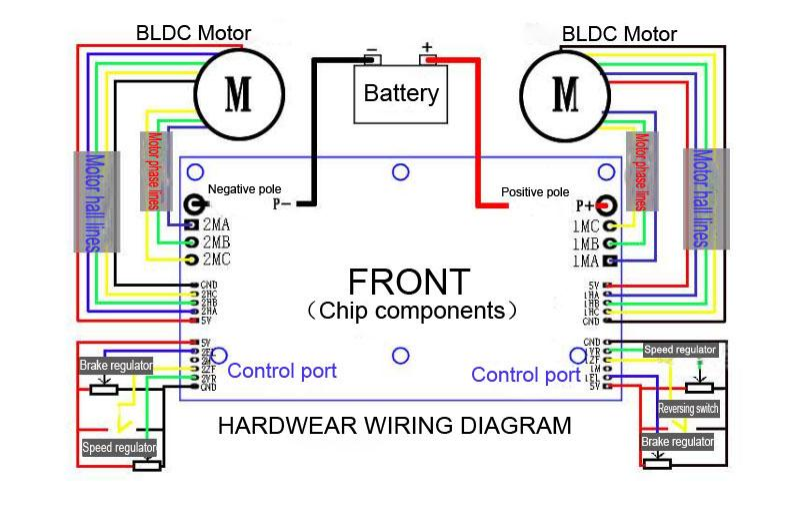

1. Control Port (Left - hand side), 2.0mm Pitch
5V — The control board internally outputs 5V and can supply an
external current of less than 300mA.
2EL — Brake control port. It is a reactive - free linear brake with an
energy - recovery function. The analog voltage for braking ranges
from 0 - 5V. When the rotational speed is constant, the higher the
braking voltage, the greater the braking force (ranging from 0 -
100%).
2M — Rotational speed signal output port. The pulse frequency is
proportional to the motor's rotational speed (the pulse ratio is
related to the motor).
2Z/F — Forward and reverse rotation control port. It has hard -
commutation. Connecting to 5V or leaving it floating makes it
rotate in one direction, while connecting to GND makes it rotate in
the other direction.
2VR — Rotational speed control port. It uses analog voltage for speed
regulation from 0V - 5V (0 - 2.5V), with linear speed regulation
from low to high. When using an external PWM for speed regulation,
it needs to share the same ground as the driver board.
GND — The internal ground of the control board.
2. Hall Port (Left - hand side), 2.0mm Pitch
GND - Negative pole of the Hall power supply
2Hc - One of the motor Hall signals
2Hb - One of the motor Hall signals
2Ha - One of the motor Hall signals
5V - Positive pole of the Hall power supply
3. Power Port (Left - hand side)
P - — Negative pole of the DC power supply
MA — One of the three - phase motor wires
MB — One of the three - phase motor wires
MC — One of the three - phase motor wires
4. Control Port (Right - hand side), 2.0mm Pitch
GND — The internal ground of the control board.
1VR — Rotational speed control port. It uses analog voltage for speed
regulation from 0V - 5V (0 - 2.5V), with linear speed regulation
from low to high. When using an external PWM for speed regulation,
it needs to share the same ground as the driver board.
1Z/F — Forward and reverse rotation control port. It has hard -
commutation. Connecting to 5V or leaving it floating makes it
rotate in one direction, while connecting to GND makes it rotate in
the other direction.
1M — Rotational speed signal output port. The pulse frequency is
proportional to the motor's rotational speed (the pulse ratio is
related to the motor).
1EL — Brake control port. It is a reactive - free linear brake with an
energy - recovery function. The analog voltage for braking ranges
from 0 - 5V. When the rotational speed is constant, the higher the
braking voltage, the greater the braking force (ranging from 0 -
100%).
5V — The control board internally outputs 5V and can supply an
external current of less than 300mA.
5. Hall Port (Right - hand side), 2.0mm Pitch
5V - Positive pole of the Hall power supply
1Ha - One of the motor Hall signals
1Hb - One of the motor Hall signals
1Hc - One of the motor Hall signals
GND - Negative pole of the Hall power supply
6. Power Port (Right - hand side)
P+ — Positive pole of the DC power supply
1MC — One of the three - phase motor wires
1MB — One of the three - phase motor wires
1MA — One of the three - phase motor wires
3. Note that the motor wires should not be too long. If the wires
are too long, signal interference problems may occur.
4. When operating with continuous large currents, heat -
dissipation issues should be noted.
Dimensional Drawing: